Design and construction of medium and deep hole blasting in quarry
1. Selection of rock drilling equipment and blasting equipment 1.1 Selection of rock drilling equipment Medium-deep hole blasting refers to blasting operations with a hole depth greater than 5 m and a hole diameter greater than 75 mm. The characteristics of the blast hole determine that the rock drilling equipment must use deep hole drilling tools. This plan uses Xuanhua Ingersoll Rand CM351 down-the-hole drill, which is suitable for various rocks with a rock hardness f in the range of 6 to 20. The borehole diameter is 115 mm, the borehole depth can reach 30 m, and the drill rod length is 3 m. 1.2 Selection of blasting equipment 1)
Explosive types and detonating charges: 2# rock ammonium nitrate explosives are used, and emulsion explosives are used for detonating charges in the presence of water. In addition, the use of columnar charges can disperse the explosives more evenly in the rock mass, which can increase the blasting volume per meter and reduce the unit consumption of explosives, thereby reducing the amount of explosives used and reducing engineering costs. 2) Detonator selection: Instantaneous electric detonators are used outside the hole, segmented detonating cords are used inside the hole, and 1st, 3rd, and 5th sections of conduits are used in the 1st to 3rd rows respectively, with a delay time of 25ms for each section. 3) Detonation power supply: GFB-1200 detonator is used for detonation. 2 Determination of blasting parameters Step factors (as shown in Figure 1, schematic diagram of blasthole parameters): step height H, chassis resistance line Wd, hole spacing a, row spacing b, hole depth L, super depth hc, filling length Lt.
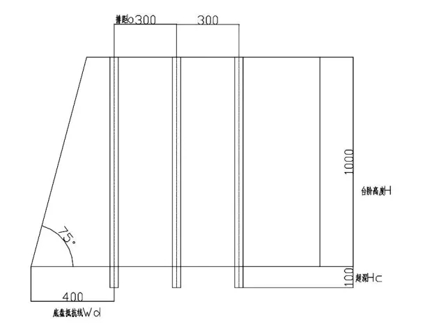
The selection of blasting parameters and hole network parameters will directly affect the blasting effect. Most of the gravel fields in a certain city are medium-hard granite mines with developed joints, a Protsky coefficient of 7~12, and good rock blastability. Drilling forms can be divided into inclined drilling and vertical drilling. The inclined drilling has uniform resistance lines and uniform blasting block size, but the operation technology is complex; vertical drilling technology is simple and fast. Since medium-deep hole blasting has not been widely used at present, and the relevant personnel in the quarry are not familiar with the essentials of the operation, it is advisable to first use a relatively simple vertical drilling method. 1) Blast hole diameter d The diameter of the drill bit of the down-the-hole drill is 115 mm, so the blast hole diameter d is 115 mm.2) Chassis resistance line Wd
①According to the safe working width of the drilling rig
Wd≥h·ctg(α+β) In the formula: h——step height, which is 10 m; α——step slope angle, in actual production, excavators are used for production, and the slope angle can reach 75°. β——The distance from the center of the blast hole to the top of the slope is 2.5 m. Then Wd≥h·ctg(α+β)=10×ctg75°+2.5=5.2 m②Calculate according to the Soviet Davydov empirical formula Wd=53·KT·d·(Δe/γ)1/2 Where: d——aperture is 0.115 m; KT——ore rock fracture coefficient, take 1.1; Δ——charge density is taken from current experience, which is 0.6 g/cm3; γ——rock bulk density, which is 2.5 t/m3; e——explosive force correction coefficient, take 1 Then Wd=53×1.1×0.115×(0.6×1/2.5)1/2=3.3 mCombined with ① and ②, take Wd=4 m3) Hole spacing a, row spacing b According to the hole area of the optimal blasting effect is 14.5 m2, according to
a=m·Wd, m is the blast hole density coefficient, the value range is 0.8~1.4, here m is taken as 1.1, then a=1.1×4=4.4 m. According to the actual value
as follows:
Take the hole spacing a=4.5 m, and calculate the row spacing b=3 m according to the hole network area. 4) Hole depth L and super depth hc In order to overcome the clamping effect of the bottom rock and leave no foundation after blasting, the blast hole needs to be over-drilled. Too deep will waste explosives, while too small will cause foundation and affect loading and unloading. Generally, the following values are taken:
hc=(0.15-0.35)d, take 0.25·Wd=0.25×4=1 m
L=h+hc=10+1=11 m5) Filling length Lt Filling length Lt=(16-32) d, take 2.8 m6) Unit explosive consumption q is taken from past experience q=0.45 kg/m3 7) Charge amount per blast hole Q ①According to the volume of ore and rock blasted per hole Q=q·a·h·Wd=0.45×4.5×10×4=81 kg ②According to the amount of explosives it can accommodate
Q=L·o p=(L-Lt)·p In the formula: Lo——Blast hole charge length, L-Lt=11 -2.8 =8.2
m; p——charge per m blasthole, charge density is 7.1 kg/m
Q=8.2×7.1=58.22 kgCombining ① and ②, take Q=58.5 kg8) Number of blastholes N
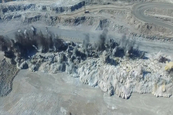
Arrange according to the specific terrain during construction. After blasting safety verification, here we simulate the calculation with 15 holes per row and 3 rows each time (the same below). Then N=15×3=45 9) Total charge Q total Q total = 45×58.5=2 632.5 kg3 Blasting safety According to the approval requirements of the quarry, the quarry is generally far away from the village, and the instantaneous noise of the blasting and the smoke from the explosion have no obvious impact on the surrounding area. These two items can be ignored in the design. The following is the necessary safety verification of the blasting seismic wave, the blasting air shock wave and individual flying stones. 3.1 The safe distance of ground structures from blasting seismic waves can be calculated according to the following formula (Formula 1) and verified according to Formula 2. Rd=Kd·fn·Q1/3 (1) V=K·(Q1/3/R)
α (2) Where: Rd——safe distance of blasting seismic wave; Kd——foundation coefficient, taken as 10 according to rock properties; fn——blasting property coefficient, taken as 0.7 according to blasting action index; Q——maximum explosive quantity of one section, which is 13162.5 kg
(According to the detonation network layout diagram, the maximum number of blast holes in one section of blasting is 15, so the maximum explosive quantity of one section of blasting is 15×58.5=13 162.5 kg) R——the distance between the blasting center and the protected building is 190 m, so Rd=10×0.7×(13 162.5)1/3=165 m
The proposed tool room and other buildings and structures are arranged in the mined area, with a distance of about 190 m, which meets the requirements. V——vibration velocity of soil points, in cm/s; K——site coefficient related to rock properties, taken as 160; R——distance between blasting center and protected building, 190 m; α——blasting seismic wave attenuation index, taken as 1.7, then V=160×(13 162.5)1/3/190)1.7=4.6 cm/s. The following safety seismic velocity values are stipulated in the "Safety Regulations for Blasting":
①Earth caves, adobe houses, rough stone houses, 1.0 cm/s; ②General
brick houses, non-seismic large block buildings, 2~3 cm/s; ③Reinforced concrete frame houses, 5 cm/s. Since all types of structures in the quarry are reinforced concrete frame houses, they meet the requirements. 3.2 Air shock wave Δp=K·(Q1/3/R)α Where: K——empirical coefficient, generally 1.48 for step blasting; α——empirical attenuation index, 1.55; Q——explosive charge in the largest section, 13 162.5 kg; K——distance from the blasting center to the protected object, 190 m, then Δp=1.48×(13 162.5)1/3/190)1.55=0.058 According to statistical data, when the air shock wave is 0.2~0.3kg/cm2, it will cause slight contusion to people. When the shock wave = 0.7~1.0 kg/cm2, it is safe for light structures.3.3 Safety distance of individual flying rocks According to the provisions of the "Safety Regulations for Blasting", the safety distance of individual flying rocks from deep hole blasting to people shall not be less than 200 m. Therefore, the safety warning range should be greater than 200 m. 3.4 Controlled blasting near fixed borders The maximum mining elevation of the quarry is 110 m, and the minimum mining elevation is +30 m, so the final height of the border is about 80 m. In order to ensure the safety and stability of the borders during the entire mining process, controlled blasting should be used near the borders. There are three methods of controlled blasting near the borders: pre-splitting blasting, smooth blasting and buffer blasting. Among the three methods of controlled blasting of borders, buffer blasting is the simplest, involving only the last row of single hole charge in the main blasting hole network. When the hole diameter is 100-115 mm, the hole spacing is 1.5 m, the resistance line (or row spacing) is 1.8 m, the line charge density is 0.37-1.12 kg/m, and the filling length is equal to the resistance line length. Using this blasting parameter can avoid serious damage to the border and ensure the safety and stability of the border. 4 Conclusion Through repeated medium-deep hole blasting tests, it was found that after the blasting parameters were used for construction, the blasted rock mass was fully broken and the blocks were uniform. The rock blocks larger than 1 m3 could be controlled within 20%, and the blasting earthquake, shock wave and flying rocks could be safely controlled. Test conclusion: 1) Compared with the handheld pneumatic drill blasting operation, the blasting volume of medium-deep hole blasting increased geometrically, the number of blasting times was greatly reduced, and the safety of construction was improved. 2) After blasting, the slag pile was concentrated, which was conducive to loading and transportation, and the production efficiency was significantly improved. 3) Compared with the handheld pneumatic drill blasting operation, the average unit consumption of explosives, the amount of detonators used, the drilling cost, the labor cost, the fuel consumption and other direct production costs of the stone were all less than those of the handheld pneumatic drill rock blasting. 4) As an experimental discipline, blasting is greatly affected by the blasting environment and rock characteristics. Only through repeated practice, analysis and research can the appropriate blasting parameters be mastered.
